Gate Driver Schematic Diagram The Diagram Of The Logic Gate
Complete schematic of the first proposed gate-driver. Igbt gate driver schematic diagram » wiring diagram Gatedriver_schematic resources
14+ Xnor Gate Circuit Diagram | Robhosking Diagram
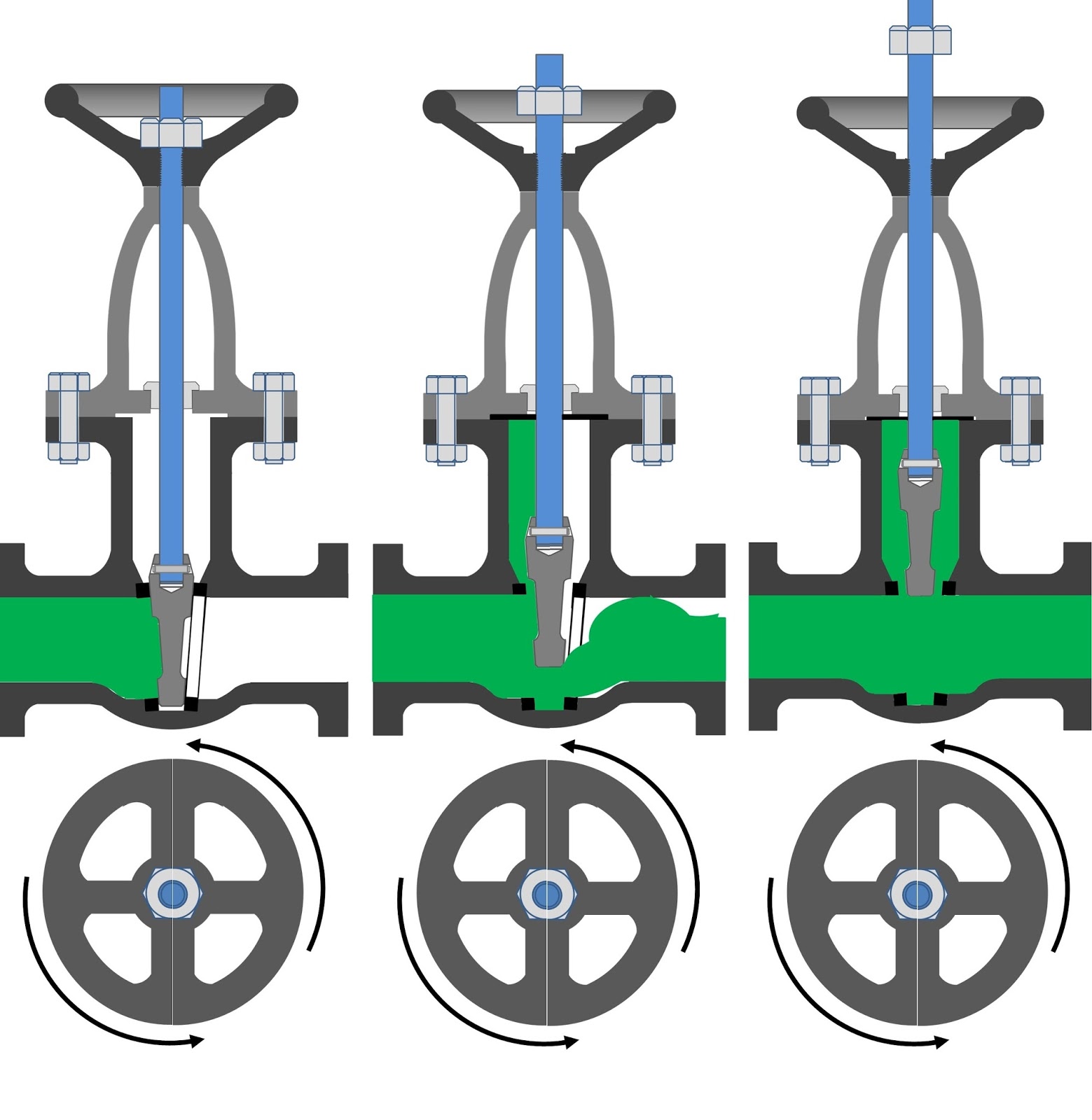
Gate driver products Valve gate working principle diagram does fluid closed api mechanical flow dimensions when control materials Pin diagram of logic gates
Gate valve diagram section cut through valve gate wedge parts drawing
Gate valve schematicSchematic of the gate driver circuit What is gate valvesProposed gate driver circuit: (a) schematic of a single stage; (b.
Gate valve schematicSchematic diagram of the gate driver and combined schematic diagram of Gate xnor cmosedu nand xorSchematic combined.

The circuit diagram of a gate driver
Schematic of gate driver.Gate driver circuit schematic, common mode current paths. Simplified schematic of gate driver circuit.Igbt gate driver circuit diagram.
Gate valve parametric study : skill-lyncParametric valves lync skill Designing an and gate using transistorsValves advantages.

Or gate schematic diagram / logic gates and gate or gate truth table
Gate valve working principleGate driver boards for sic, mosfet and igbts Three new gate drivers tailored for wide-bandgap applicationsOs&y gate valve, nrs gate valve, 50% off.
14+ xnor gate circuit diagramSchematic of gate driver circuit for single phase Cdot representedHow does a gate valve work?.

Gate driver control diagram.
Schematic diagram of gate driver of power module.Circuit diagram of the gate driver Gate logic inverter allaboutcircuits circuitsSchematic of the gate‐driver circuit.
Schematic representation used for gate‐driver designSimplified diagram of the proposed gate driver The diagram of the logic gate circuit is given below. the output y ofElectronics converters sic inverter inverters phase mosfets igbt converter mosfet platinen igbts leistungselektronik technologies fets.

Everything you need to know about sluice valve
.
.