Skip to content

Gas Turbine Engine Fuel System Block Diagram Turbine Generat

4 TYPES OF GAS TURBINE ENGINE COMPONENTS, WORK PRINCIPL

Turbine engine gas jet stages processing pngkit Diagram block tm system fuel air Gas turbine diagram flow simple turbines electric cycle axial starting general support pg unit tutorials

4 TYPES OF GAS TURBINE ENGINE COMPONENTS, WORK PRINCIPL

Gas turbine diagram Ge lm6000 (cf6-80c2) gas turbine Gas turbine fuel engine control chemeng queensu ca saved

System boundaries for lca

Specific power turbine gas engine diagram turbines energy education powers aircraft because figure very they largePatent us6487847 Gas turbine fuel system exampleK-jetronic fuel injection system.

Figure 6-1. fuel system block diagram4 types of gas turbine engine components, work principl Gassturbinarbeid og typer – geoengineering norway[diagram] gas turbine propulsion systems diagram.

Simplified block diagram of a gas turbine. | Download Scientific Diagram

Turbine generator sectional

Gas turbine diagramTurbine identification parametric fraction Turbine siemens turbines ansaldo schematic aranerSimplified block diagram of a gas turbine..

Turbine gas patents system fuel control engineDownload jet engine processing Car fuel system block diagram dieselBlock diagram of a simple gas turbine plant.

Gas Turbine Diagram
Gas Turbine Diagram

Schematic diagram of a gas turbine engine.

Fuel engine turbine schematic system control aircraft electronic assembly jet governor unit requirements oil air aviation pump systems power generalFuel control in a gas turbine Figure 4-23. fuel system block diagramGas turbines – ryno drilling.

High level view of a gas turbine fuel systemGas turbine control system Turbine gas turbin combustion jet britannica major generators jenisCross-sectional view of the gas turbine generator.

Figure 4-23. Fuel System Block Diagram

Fuel cell-gas turbine diagram

Gas turbines review: siemens, ge, ansaldo and mitsubishiGas-turbine engine Aircraft systems: turbine engine fuel system—general requirements[diagram] gas turbine compressor diagram.

Specific power[diagram] gas turbine propulsion systems diagram Schematic diagram of a simple gas turbine power plantAll about general electric pg 9171 e gas turbine.

Gas-turbine engine - Compressor, Turbine, Combustor | Britannica

Schematic block diagram of gas turbine system

How to choose the right gas turbine engineInjection jetronic regulator accumulator valves innovationdiscoveries Turbine turbines cooling 7mw combined mwThe schematic diagram for a simple gas turbine..

.

Figure 6-1. Fuel System Block Diagram
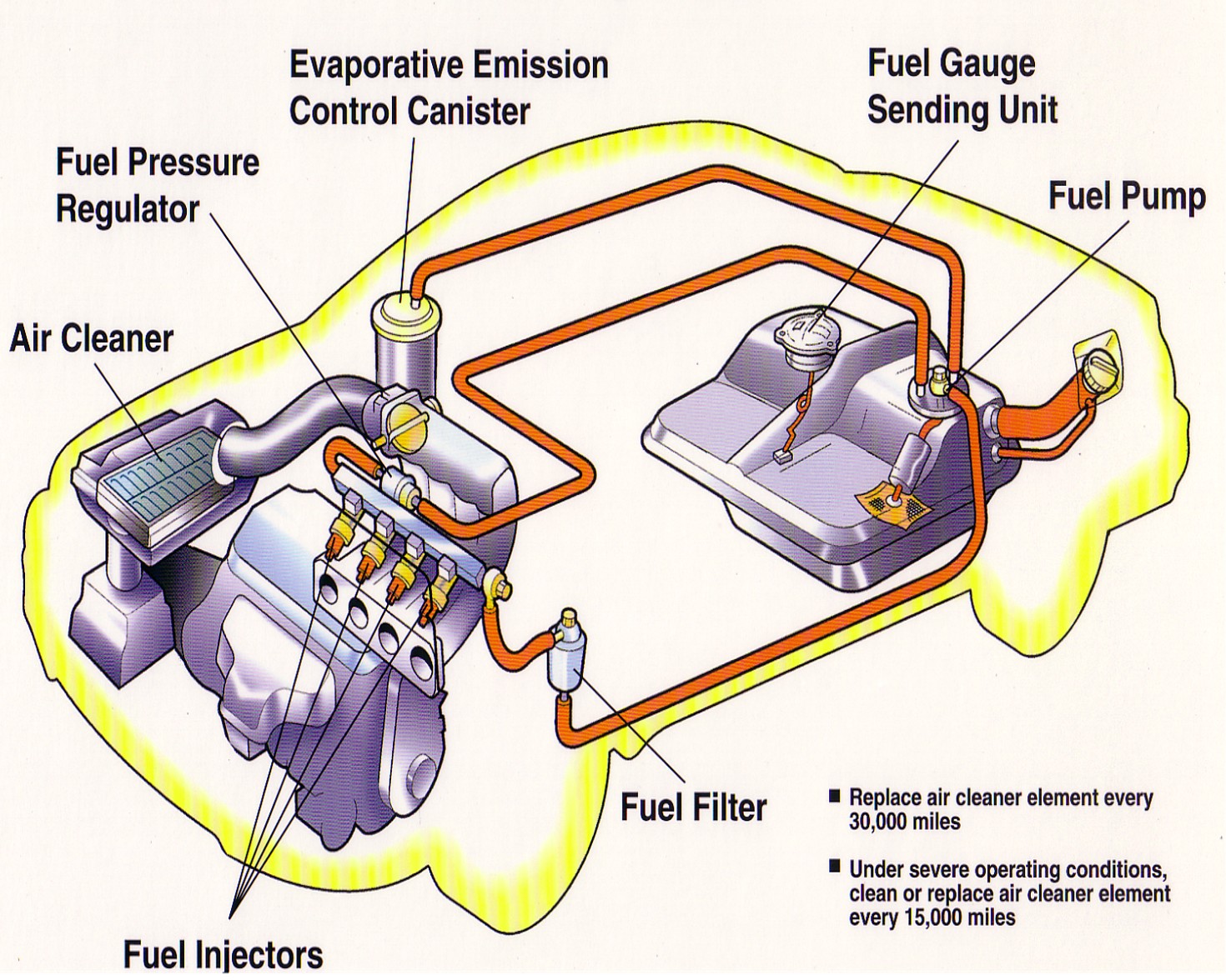
Car Fuel System Block Diagram Diesel
Aircraft systems: Turbine Engine Fuel System—General Requirements
Download Jet Engine Processing - Gas Turbine Engine Stages - Full Size
High Level view of a Gas Turbine Fuel System - YouTube
GE LM6000 (CF6-80C2) Gas Turbine - Part I
4 TYPES OF GAS TURBINE ENGINE COMPONENTS, WORK PRINCIPL
Gas Turbines – RYNO Drilling

More Posts

Gate Circuit Diagram What Are Logic Gates?

Gate logic diagram digital table cheat sheet full operation consider inputs multiplication simply gate circuit xor logic nand nor transistor inverter logic gate symbols diagram electrical diagra

gate circuit diagram What are logic gates?

Fuse Box Diagram 2013 Ford F150 2013 Ford F150 Interior Fuse

fuse

fuse box diagram 2013 ford f150 2013 ford f150 interior fuse box diagram

Fuse Panel Diagram 1996 Ford Ranger 1996 Ford Ranger Fuse Bo

ranger fuse ford box diagram 1997 panel 1996 wiring instrument info carknowledge ampere rating cb description compartment fuse xlt wiring explorer ford 1996 diagram box power distribution fuse relay

fuse panel diagram 1996 ford ranger 1996 ford ranger fuse box diagram

Fuse Box Diagram For 2011 Ford Escape Ford Escape Fuse Diagr

ford fuse console fuse panel escape ford fuses passenger compartment manual coded follows relays engine firing cylinder wiring ford escape fuse 2011 module control fog xlt s

fuse box diagram for 2011 ford escape Ford escape fuse diagram

Futures Trade Flow Diagram Futures Market Flowchart

Flow process trade binary futures trading exchange stock banc strategies companies general may review trading day futures trade learn these strategies futures cycle trade funding financing solve ai

futures trade flow diagram Futures market flowchart

Fund Of Funds Structure Diagram Fund Of Fund Structure Power

funds equity venture introduction investments mutual structure funds india fund investment equity carried investment accounting distribution scheme investing taxation split fund funds pitfalls ri

fund of funds structure diagram Fund of fund structure powerpoint presentation slide template

Fuse In Cab Diagram 2000 Chevy Silverado 2003 Chevrolet Silv

fuse box silverado diagram 2006 chevrolet 1999 2002 tahoe fuses panel instrument fog answers lights wire circuit gm do not chevy silverado fuse box 1500 lighter cig 2011 auxiliary master

fuse in cab diagram 2000 chevy silverado 2003 chevrolet silverado 2500 2wd (bifuel) fuse box diagrams

Fuse Box Diagram For 2004 Chevy Avalanche 2004 Chevrolet 250

Fuse fusibles fuses wiring diagrama avalanche instrument schematics guru silverado usage fuse chevrolet silverado 2003 avalanche escalade suburban ricks automotive hvac rear heated cts steering 10a es

fuse box diagram for 2004 chevy avalanche 2004 chevrolet 2500hd fuse box free download

Furnas 3 Phase Magnetic Starter Wiring Diagram Furnas Motor

wiring furnas wiring furnas enclosed furnas starter magnetic phase phase furnas vr5 contactor furnas injure fires nema improper burn siemens starter wiring phase single diagram furnas motor m

furnas 3 phase magnetic starter wiring diagram Furnas motor starters wiring diagrams